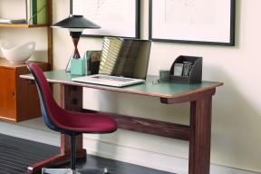
The idea for this versatile, adjustable worktable was inspired by Carolyn, a budding journalist who requires extra clearance under her desk for her wheelchair. Carolyn also wanted a table that could be dismantled quickly to make it more convenient to move between home and various offsite work locations. These design requirements resulted in a unique piece of furniture that can be reconfigured to serve a variety of uses in your home or office.
When the tabletop is lowered, this table functions as a conventional desk with plenty of room on top for paperwork and a computer. Raise the tabletop using the hassle-free adjustment mechanism to get a handy standup workstation that’s perfect for crafts, serving food or to ease the strain on a sore back after sitting all day.
The workstation goes together with knockdown hardware, so the entire unit can be dismantled in less than a minute by simply lifting off the tabletop, lowering the extension rails and removing the cross brace. I’ve come up with innovative construction techniques that make this project a snap to build, so let’s get started.
Begin by building the leg assemblies for the base. As you can see from the plans, the lower sections of the legs are made of wide columns attached to long foot segments with mortise-and-tenon joints. The interior of the columns are hollow to form channels for the extension arms that allow the tabletop to be raised and lowered. Cantilevered support arms cap the top of the extension arms are that the removable tabletop rests on.
Start by cutting the column sides and spacers for the hollow columns. The assembly sequence for these parts is important. Don’t complete the steps out of order or you may find yourself in a bind.
Grab your glue bottle and some clamps to fasten the spacers to the interior surfaces of the inside column sides. Before the glue has set, make sure the spacers are flush with the outside edges along their entire length. If these parts are misaligned, the width of the channel won’t be uniform from top to bottom, which could cause the extension arms to bind as they move.
For smooth movement, it’s also important to clean up any glue residue that squeezes out on the inside of the channels. After the clamps are removed, install a dado blade in your tablesaw to notch out the rear edges of the columns. These notches are for the ends of the horizontal cross brace that will stretch between the leg assemblies. This is an example in which following the steps in the proper order is critical; it would be impossible to complete this task on the tablesaw if the outer column side was attached first.
The next step is to cut out a pair of 5"-wide x 4"-long blocks from 3/4"-thick material to serve as the column tenons that make the connections with the foot assemblies. Glue and clamp the column tenons in place with 2"-long tongues protruding from the bottoms of the channel slots. Add the remaining side panel to each assembly. Before the glue dries, wrap a rag around the end of a stick to wipe up any residue from the interior.

Your next job is to cut the extension arms to size from 3/4"-thick material. At this stage, the parts will be too thick to slide smoothly in the column channels, so head over to the thickness planer to remove 3/32" from one face on each. This step should provide just enough clearance to prevent binding in the channels and allow for the finish that will be applied later on. When you’re satisfied with the fit, move on to the next step.
A quick look at the plans shows how the foot segments and support arms are made by laminating two layers of 1"-thick material to form solid blanks. I designed them this way so the tablesaw could be used to notch out the mortises that will house the column tenons and extension arms. The tablesaw method is much easier and quicker than traditional mortising techniques involving time-consuming work with hand chisels.
Cut out enough blanks to make the foot segments and support arms. Next, install a dado blade in the tablesaw to notch out the mortises. Before you work on the blanks, make test-cuts on scrap and clamp together the two halves to check the fit with the corresponding tongues. It’s also important that the extension arms be slightly thinner than the column tenons to create sliding clearance. You’ll need to lower the tablesaw blade a smidgen when creating the notches on the support arms.
When all this work is done, apply an even coat of glue to the blanks and clamp the parts together in pairs. Try to keep the glue out of the mortise openings.
When the blanks are dry, lay out decorative tapers and rounded corners at the locations shown in the plans. Make the necessary cuts to shape the parts, then sand the edges to clean up the tool marks left behind by the saw blade. The bottom of the foot assemblies are notched to form 3"-long foot pads on each end. The easiest way to create these notches is to nibble away at the waste material by making repeated passes over a dado blade. When the dust has settled, dry-fit the connecting parts one last time to make sure there are no problems that need to be sorted out before final assembly. If all is well, apply glue to the walls of the mortise openings and slip the column tenons and extension arms into place.
Round clamp knobs with threaded inserts lock the support arm assemblies in place when adjusting the tabletop’s height. The knobs tighten into flanged, threaded inserts installed in the inward faces of the extension arms. I included three height options, but you can create more. You can also use different settings if mine don’t suit your specific needs. The only limitation is that at least 8" of the extension arms must remain in the column channels to support the tabletop adequately.
To install the flanged inserts, drill a pair of 1/4"-diameter holes on the inside face of each column side to provide access for the knob shafts. Refer to the plans for correct locations. Next, slide the extension arms into place and use a 1/4"-diameter drill bit in the access holes you just prepared as guides to mark the locations for the inserts. Don’t drill too deeply right now—a slight dimple is all that is required to mark the spots. I used spacer blocks to prop up the support arms when completing this procedure.
After marking the insert locations, remove the extension arms and prepare for installation of the insert parts. First, use a 1/2"-diameter Forstner or brad-point bit to drill shallow, 1/16"-deep holes on each extension arm to recess the insert flanges. Either of these bits is a good option because both create holes with flat bottoms. Next, switch to a 5/16"-diameter bit and drill 9/16"-deep pilot holes to receive the insert threads. Twist the inserts into place using a hex key and try locking the extension rails into position. To prevent the shoulder of the knobs from biting into the surface of the columns, I used 1/4"-diameter washers between the knobs and the wood to distribute the force over a wider area.
You have two leg assemblies ready that won’t do you much good if you can’t connect them. We’ll solve that problem right now with a sturdy, horizontal cross brace. Cut the brace to size from 3/4"-thick material and try its ends in the column side’s notches you created earlier. To achieve a solid connection, you want the fit to be snug.
Drill a couple of 1/4"-diameter holes in both the ends of the cross brace to receive the winged knobs that attach the brace to the column sides. Use these holes as guides to mark locations for the threaded inserts in the column spacers. Remove the cross brace, then drill the holes for the flanges and the pilot holes for the threads, just like before. Install the inserts and attach the cross brace using the winged knobs.

The tabletop is easy to build. It consists of a 3/4"-thick Baltic birch substrate covered with a layer of plastic laminate. I like using laminate for the surface of utility tables because it’s durable and easy to clean up. The edges of the tabletop are wrapped with solid-wood trim, and a support rib is mounted on the bottom to make the plywood more rigid.
Begin by cutting the plywood to size at the tablesaw, then cut out a piece of plastic laminate that overhangs the edges by roughly 1/2" on all sides. I’ve found that most home-improvement stores no longer stock convenient 2' x 4' sheets of laminate, so I turned to a local countertop manufacturer to purchase this material; countertop fabricators often have small offcuts that they’re willing to sell for bargain prices. The laminate is bonded to the substrate using contact cement. Apply the contact cement to both surfaces and let it dry completely before pressing the laminate into place. Use a roller or the palm of your hand to make sure a uniform bond is achieved over the entire surface. Now, grab your router and install a bearing-guided, flush-trim bit to trim off the excess laminate from the edges.
To make the edge trim, start with a board that is about 5" wide x 50" long. After surface-planing it to match the exact thickness of your tabletop, joint all edges. Next, install a 45° bearing-guided bit in your table-mounted router to mill a 1/8" bevel on all of the edges.
Next, head over to the tablesaw to rip a 3/4"-wide strip from one long edge of the board. After rejointing the edge of the remaining material, repeat the entire process to create more strips. This process yields more trim than you’ll need, but having extra is never a bad idea. Cut the trim to length with 45° mitred ends and glue the edging to the perimeter of the tabletop.
Next up is the support rib on the underside of the tabletop. Cut the rib to size, then form a 11⁄2"-radius decorative curve on both ends with the bandsaw or a jigsaw. The rib runs along the length of the tabletop, 6" from the rear to keep it well out of the way of knees and chair arms. I fastened the support rib to the tabletop with 11⁄2"-long round-head screws. When you drill the pilot holes for the screws, you will also need to countersink the heads by 1".
The tabletop is mounted on the support arms using dowel pins to anchor it with no glue. This setup makes it easy to remove the tabletop when you’re on the move or want to adjust its height. First, drill 3/4"-deep x 1/2"-diameter holes in the top of the support arms to seat the dowel pins. (The plan details show the recommended locations.)
Now, for the tricky part: marking the corresponding hole positions on the bottom of the tabletop. You need to be precise here, or the dowel pins won’t engage properly. The most accurate way is to use dowel centres—metal plugs manufactured to fit in the holes for most standard dowel sizes; they have sharp points in the centre that make an impression on mating parts brought together overtop of them. You can purchase an entire set of dowel centres for just a few bucks at most tool retailers.
Before positioning the tabletop on the support arms to mark drilling locations, make sure the legs are square to the support rib. When you’re happy with the arrangement, press down on the tabletop to make your marks.
Lift the tabletop off, then drill 1/2"-deep holes in the marked locations with the same 1/2"-diameter bit you used previously. Cut 1 1/4"-long pins from a 1/2"-diameter dowel and glue the pins in the support arm’s holes. If you round the ends of the pins with sandpaper, it will make it easier to slip the dowels into the corresponding holes in the tabletop. I also recommend sanding the sides of the dowel pins to achieve a more relaxed fit, which also makes it easier to remove the tabletop when you want to adjust the height or dismantle the workstation.
I applied a coat of red mahogany gel stain, followed by four coats of wipe-on polyurethane. I sanded with 400-grit paper between coats of polyurethane to achieve a silky smooth finish. Don’t forget to tape off the edges of the laminate before you start, as stain is difficult to remove. After the last coat of polyurethane has cured for about a week, buff the extension arms with a little paste wax to make them glide smoothly in the column channels. You will recall that we intentionally sized the cross brace to achieve a tight fit in the column side’s pockets. Now that the finish is applied, you may find that the cross brace is too snug and will no longer engage in the openings. This problem is easily solved by using a sharp chisel to pare off a thin layer of finish from the ends on the inside face. Don’t be concerned if you expose bare wood, because the ends will be concealed in the column notches. All that remains is to reattach the leg assemblies and tabletop so you can put this resourceful workstation to good use.
1. Create dimples on the extension arms with the tip of a drill bit to mark the locations of the flanged, threaded inserts. A spacer sets the position of the extension arms while completing the task.
2. Drill 1/16"-deep holes in the extension arms for the flanges of the threaded inserts.
3. Drill deeper pilot holes in the extension arms with a 5/16" bit to receive the inserts.
4. Install the inserts in both extension arms and column sides with a hex wrench.
| Part | Material | Size (T x W x L*) | Qty. |
|---|
You will need |
|||
|---|---|---|---|
| Column sides | red oak | 1/2" x 8" x 21" | 4 |
| Column spacers | red oak | 3/4" x 1 1/2" x 21 | 4 |
| Column tenons | red oak | 3/4" x 5' x 4' | 2 |
| Extension arms | red oak | 1" x 5" x 21" | 2 |
| Foot segments | red oak | 1" x 2 1/2" x 22 1/2" | 4 |
| Support arms | red oak | 1" x 2 1/2" x 22 1/2" | 4 |
| Cross brace | red oak | 3/4" x 4" x 43 1/4" | 1 |
| Top | Baltic birch ply | 3/4" x 22 1/2" x 46 1/2" | 1 |
| Plastic laminate | 1/16" x 23" x 47" | 1 | |
| Short edge trim | red oak | 13/16" x 3/4" x 24" | 2 |
| Long edge trim | red oak | 13/16" x 3/4" x 48" | 2 |
| Support rib | red oak | 3/4" x 2" x 38" | 1 |
| Dowel pins | hardwood | 1/2"-diameter x 1 1/4"-long | 4 |
| Round knobs | Lee Valley #00M56.11 | 4 | |
| Winged knobs | Lee Valley #00M51.02 | 4 | |
| Flanged inserts | Lee Valley #00N10.13 | 16 | |
| Washers | 1 1/4"-diameter (outside) | 8 | |
* Length indicates grain direction
Tablesaw
planer
jointer
table-mounted router
drill/driver
bandsaw or jigsaw
Recommendations

canadianhomeworkshop.com is part of the Blue Ant Media
Canada Network
© 2024 Blue Ant Media
More information
Social Media & RSS


Our other sites


No comments
To leave a comment, please log in
Don't have an user account? Register for free